
Views: 0 Author: Site Editor Publish Time: 2026-11-13 Origin: Site


Industrial automation requires precise positioning data. You rely on accurate sensors to keep production moving safely. In foundries, steel mills, and bulk material handling facilities, environments remain notoriously harsh. Extreme conditions routinely compromise standard sensor arrays. Airborne particulate matter blinds delicate lasers without warning. Structural vibrations cause optical encoders to fail abruptly. Operations suffer immediately when these critical components degrade. Facilities face unplanned downtime and forced manual overrides. These sudden failures create severe safety risks for your team. Our guide helps maintenance directors and automation engineers solve this exact problem. We provide an evidence-based framework for evaluating harsh-environment crane positioning. You will learn about the operational advantages of a robust non-contact solution. We show how a Gray Bus Positioning System significantly outperforms traditional optical or RF alternatives. This approach secures continuous production without relying on fragile, easily obscured sensors.
l Traditional positioning methods (lasers, optical encoders) degrade rapidly in environments with heavy particulate matter, requiring unsustainable maintenance cycles.
l A Gray Bus Positioning System uses non-contact absolute encoding and does not require an optical line of sight. Suitability for dust, heat, and vibration must be assessed against the equipment configuration and site conditions.
l Evaluating a harsh-environment positioning solution requires looking beyond initial CapEx to focus on Total Cost of Ownership (TCO), specifically factoring in reduced maintenance interventions and increased automated uptime.
l Successful implementation depends heavily on structural alignment during installation and seamless integration with existing safety PLCs and collision avoidance systems.
Airborne dust, heavy grease, and thick smoke create significant challenges for automation. These pollutants rapidly coat laser reflectors and optical barcode tapes. Light-based sensors require a clear line of sight to function. They lose signal integrity as soon as debris blocks their lenses. Standard automated material handling systems depend heavily on continuous data streams. Signal loss leads to erratic, unpredictable crane behavior. Operations halt when PLCs cannot verify exact load coordinates. Cleaning these optical sensors becomes a frustrating, endless chore. Maintenance teams must climb onto crane bridges frequently. They wipe down reflectors just to keep production running through a single shift.
High-heat environments introduce complex physical challenges for precision sensors. Ladle cranes operate directly above molten metal. These zones generate intense thermal gradients. Extreme heat creates refractive air pockets. Refraction warps laser sightlines, causing false distance readings. Continuous structural runway vibration adds another layer of failure. Overhead cranes naturally flex and shift while lifting heavy loads. This mechanical movement easily misaligns target-based sensors. Optical encoders physically coupled to wheels also suffer. They experience rapid mechanical wear from constant shock. They eventually slip, leading to severe positional inaccuracies.
Intermittent signal loss creates a cascading effect across your facility. Sensor drift forces immediate reliance on manual operation fallbacks. Manual handling severely reduces overall facility throughput. It also eliminates the safety layers provided by automated collision avoidance software. You expose valuable equipment to collision risks. Operators cannot judge exact stopping distances as effectively as programmed PLCs. We see excessive maintenance labor wasted on recalibration. Technicians spend countless hours realigning fragile sensors. You lose valuable production time during every adjustment phase. Sensor suitability must be verified for the crane duty cycle and operating conditions.
l Forced transition from automated cycles to slower manual overrides.
l Increased risk of load collisions due to delayed sensor response times.
l High labor hours consumed by daily optical sensor cleaning.
l Premature mechanical wear on crane drives caused by erratic braking.
l Software faults triggered by missing or corrupted position packets.
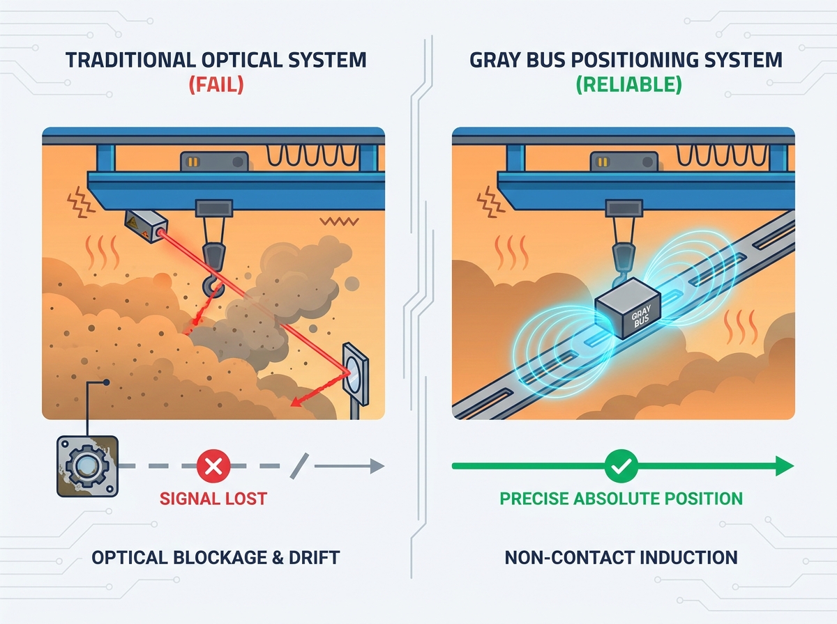
A Gray Bus Positioning System uses non-contact electromagnetic coupling and Gray-code address detection. The Gray bus is installed along the equipment travel path and works with an antenna box, encoder, and decoder. The encoder transmits address signals, and the decoder converts the received signals into absolute position data for the control system. Wuhan Forward offers ground detection and on-board detection configurations. Its high-precision Gray bus uses a rigid inner liner, a precision CNC-machined base plate, and high-precision molded threading cards without foam filler. The published resolution is 1 mm, with position detection accuracy specified as 1 mm.
Gray bus positioning does not require an optical line of sight. Its non-contact detection principle makes it suitable for dusty industrial environments where optical paths may be obscured. Wuhan Forward specifies sealed, non-metallic outdoor Gray bus components, fixtures, and antenna boxes, with acid and alkali corrosion resistance. Site-specific contamination, temperature, and installation conditions should still be reviewed before selecting the system.
The system provides continuous absolute position detection without cumulative error. Because the address is absolute, position detection does not depend on rebuilding an incremental count after a power interruption. Restarting automatic crane operation must still follow the control system recovery procedure and safety checks. Wuhan Forward specifies an antenna-to-bus gap of 30–300 mm front and back and a permitted up-and-down offset of ±100 mm. These installation allowances help accommodate equipment movement, provided the specified clearances are maintained.
Operational Reliability Chart
Environmental Factor | Laser Distance Meters | Optical Encoders | Gray Bus System |
Heavy Dust / Smoke | Fails (Requires Cleaning) | Degrades Rapidly | No optical line of sight required |
High Temperature Gradients | Signal Refraction / Drift | Mechanical Warping | Stable Operation |
Severe Vibration | Target Misalignment | Physical Wear / Slipping | Within specified installation clearances |
Power Outage Recovery | May Require Homing | Depends on encoder type and system design | Absolute position detection after valid data is restored |
You must establish baseline operational requirements for your specific facility. Different material handling tasks demand varying levels of precision. Automated coil handling in steel yards requires millimeter-level accuracy. The system must guide massive grabs into very tight spaces. General zone tracking for simple collision avoidance allows looser tolerances. You need to map these exact needs before selecting hardware. A properly configured Gray Bus Positioning System handles both extremes effectively. It delivers highly repeatable data streams for synchronized multi-crane lifts. Assess your duty cycles carefully to ensure the chosen system aligns with production goals.
Evaluate sensor durability, inspection access, and maintenance requirements against the actual duty cycle. Wuhan Forward describes sealed, non-metallic outdoor components and non-contact operation that avoids reader-to-track wear and slippage. Obtain project-specific maintenance guidance and reliability data from the supplier. Set inspection intervals from site conditions and commissioning results rather than assuming a fixed cleaning or inspection schedule.
Check the PLC interface and network requirements before selecting a positioning configuration. Wuhan Forward lists RS232C, Modbus, Modbus RTU, PROFIBUS, PROFINET, DeviceNet, Ethernet using TCP/IP through an RJ45 interface, and SSI among its communication options. Confirm the exact interface supplied for the project; the availability of an Ethernet connection alone does not establish support for every industrial Ethernet protocol.
Position measurement is one part of the overall crane control and safety architecture. Assess the required safety functions and applicable standards at system level. Where SIL or PL requirements apply, verify the relevant component documentation and validated architecture rather than assuming a standard positioning device carries a particular safety certification. Gray bus position data can support motion control and anti-sway integration, while protective functions require their own engineering assessment.
Technical Specification Guidelines
Specification Metric | Industrial Requirement | Common Application Benefit |
Protocol Support | PROFINET and other confirmed project interfaces | Seamless PLC integration without delay. |
IP Rating | Confirm the supplied component protection rating | Protection against water jets and fine dust. |
Resolution | 1 mm published resolution | Precision placement for automated grabs. |
Reading Gap | 30–300 mm front and back; ±100 mm up and down | Accommodates natural runway shifting. |
You must address the physical realities of retrofitting heavy equipment. Installing a Gray Bus track requires careful planning. You mount the track along the entire length of the crane runway. You must assess the structural integrity of your existing girders first. Older facilities often have warped or heavily modified steel structures. Determine the best mounting bracket styles for your specific beams. Weld-on brackets provide permanence in high-vibration zones. Clamp-on designs offer flexibility without altering the main steel. Your engineering team must verify clearance parameters before beginning the hardware installation.
Install the Gray bus and antenna according to the supplier installation requirements. Maintain suitable support, alignment, and clearance throughout the travel path, including under operating vibration and structural movement. Check the specified 30–300 mm front-and-back gap and ±100 mm up-and-down allowance across the full operating range. Address thermal movement and mounting details through the project engineering design, and verify continuous address detection during commissioning.
Installing full-length runway tracks requires deliberate scheduling. You cannot disrupt critical path production for a sensor upgrade. We highly recommend utilizing scheduled maintenance turnarounds. Break the project down into manageable linear segments.
1. Preparation Phase: Install mounting brackets during an approved maintenance window with the required equipment isolation and access arrangements.
2. Track Installation: Mount the busbar sections during a weekend shift when crane activity drops.
3. Antenna Mounting: Attach the reader module to the crane bridge during a standard preventative maintenance window.
4. Network Integration: Wire the system into the main PLC cabinet and assign network IP addresses.
5. Calibration and Testing: Run the crane through extreme travel limits to verify data packet consistency before handing it back to production.
Advanced positioning solutions carry different upfront dynamics than basic laser distance meters. Basic lasers seem cheaper initially. However, basic sensors fail constantly in harsh conditions. You must look closely at long-term performance metrics. Reliable systems eliminate massive hidden operational drains. Evaluate how much revenue you lose during unexpected sensor failures. Calculate the direct labor hours wasted on continuous cleaning cycles. A robust system fundamentally changes how your maintenance team operates. They stop fighting sensor faults and focus on proactive equipment health.
You build a strong business case by focusing on recovered downtime. Unplanned crane stoppages bottleneck entire facilities. Eliminating these stoppages drives immediate production gains. Removing sensor cleaning labor frees up your technical staff. They can tackle critical mechanical tasks instead. Reliable positioning data also reduces collision-related mechanical wear. Smooth, automated braking extends the life of brake pads, wheels, and drive motors. You protect your capital equipment from operator errors. Stable automation yields higher daily throughput and reduces scrap rates consistently.
Selecting the right hardware partner matters as much as the technology itself. You should evaluate vendors based on their specific industrial experience. Ask for case studies from environments matching yours exactly. A vendor familiar with cleanrooms cannot help a cement plant. Look for proven success in steel mills, foundries, or bulk material ports. Verify the availability of local commissioning support. Complex network integration sometimes requires expert on-site troubleshooting. Scrutinize their warranty terms for high-heat and high-vibration applications. A confident vendor backs their hardware against the harshest environmental realities.
l Request physical samples of the busbar to test structural rigidity.
l Verify compatibility with your exact PLC brand and firmware version.
l Ask about spare parts availability and average shipping lead times.
l Ensure the vendor provides comprehensive installation manuals and alignment tools.
Reliable crane positioning requires a measurement system matched to the operating environment. Gray bus positioning offers non-contact absolute detection without an optical line of sight and is suitable for demanding industrial applications. Review dust exposure, thermal conditions, structural movement, communication requirements, and installation clearances before selecting a configuration. Audit existing sensor maintenance logs and downtime records to assess whether an upgrade is justified.
A: Gray bus positioning uses non-contact electromagnetic address detection to provide an absolute position. Optical encoders use optical sensing internally; when a position measurement depends on a wheel or mechanical transmission, slippage or wear can affect the resulting position. The Gray bus antenna does not touch the bus, and the measurement does not require an optical path along the runway.
A: Yes. Curved Gray bus tracks can be used for rotation detection on stacker-reclaimers and port cranes. The track arrangement, antenna installation, and detection configuration must suit the specific rotating equipment. This system is not intended for transfer cars.
A: The system provides absolute position detection without cumulative error, so it does not need to rebuild an incremental position count through a homing run solely because power was lost. After power restoration, the controller must verify valid position data and complete the required safety and restart checks before automatic movement resumes.


